

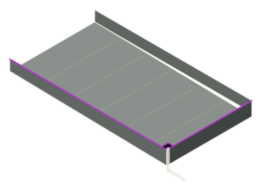
What a condensate drain pan does
A cooling coil pulls moisture out of the air; chilled-water pipes sweat wherever insulation is damaged; liquid-cooled data halls run secondary-fluid pipework over the white space. A drip tray catches that water before it reaches a ceiling, a panel or a server rack. Typical locations:
- AHU drain pan under the unit or coil section in the AHU room.
- FCU and VRF drain pans under ductable, cassette and hi-wall indoor units.
- Chilled-water pipe drip trays under pipe runs, valves and manifolds in plant rooms and risers.
- Data centre drip trays under chilled-water and liquid-cooling pipework in hot and cold aisles.
Sizing an AHU drain pan or HVAC drip tray
| Item | The rule | Pioneer standard |
|---|---|---|
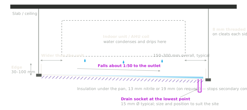
| Plan size (equipment pan) | Larger than the unit, so nothing misses the pan | Typically 150–300 mm larger overall — a 900 × 450 mm unit gets a 1200 × 750 mm tray |
| Pipe-run tray width | Wider than the pipe and its insulation | 100, 150, 250, 300, 500, 600, 700 and 750 mm |
| Length | One continuous tray per run | Up to 5000 mm per tray, joined with couplers |
| Edge (collar) height | Deep enough to hold a leak until it drains | 30, 50, 63, 75 and 100 mm — usually 50 or 75 mm under HVAC units, 63 or 100 mm under data-centre pipework |
| Slope | ASHRAE 62.1: at least 10 mm per metre toward the outlet | About 1 in 50 (20 mm per metre) on approved shop drawings |
| Drain outlet | At the lowest point, large enough not to overflow; trapped where the pan is under negative pressure | 15 mm Ø drain socket typical; size, position and hose point to suit the site |
| Insulation | A pan under a chilled-water unit gets cold and sweats | 13 mm nitrile rubber or 19 mm insulation underneath, on request |
| Sheet thickness | To suit the tray size and hanging | 0.8, 1.0, 1.2, 1.5, 1.6 and 2.0 mm |
Corners, joints and hanging
A drain pan fails at its weakest point — a corner, a joint or the outlet — so specify those, not just the size.
- Leak-tight corners. Ask for the corner detail on the GA drawing you approve. Pioneer sends a data sheet and GA drawing for approval with every drip tray order.
- Continuous runs. Long trays are joined with plate couplers (25 × 200 × 2 mm, four M8 fasteners each; SS 304 fasteners on stainless trays), so water flows to the outlets without being dammed at a joint.
- Hanging. Cleats for 8 mm threaded rods on each side, or L-clips and 30 × 30 × 5 mm angles.
- Leak detection. In a data centre drip tray, leave room for the leak-detection cable or probes.
Choosing the drip tray material
| Material | Choose it when |
|---|---|
| SS 304 (ASTM A240, mirror finish on one side) | The tray must stay clean and rust-free for the life of the building — data halls, pharma, food, and anywhere a leak would be costly. |
| Hot-dip galvanised steel | The specification asks for a heavy zinc coat and rules out electroplated GI. |
| Pre-galvanised GI, 120 / 180 / 275 GSM | HVAC units inside buildings. 275 GSM is the coating US specifications call G90. |
| Powder-coated GI, epoxy-coated GI or PPGI | You want a painted barrier over the zinc, or a colour that matches the services. |
| Aluminium or epoxy-coated aluminium | Large pans where weight on the slab or the hangers matters. |
Specification clauses for your BOQ
Copy a clause and adjust it to your schedule; words in [brackets] are alternatives. Full specifications are on the drip trays page.
Data centre pipework — SS 304 / HDG
Chilled-water and liquid-cooling pipework in data halls
1. Drip trays shall be provided under chilled-water and secondary-fluid pipework where shown on the drawings, fabricated from SS 304 sheet [hot-dip galvanised steel] 1.2 mm [1.5 mm] thick.
2. Trays shall have a turned-up edge of 63 mm [100 mm] and shall be joined with plate couplers into one continuous tray that drains to the outlets.
3. Tray lengths shall be up to 5000 mm, width as per the pipe routes on the drawings.
4. Each tray run shall fall about 1 in 50 to drain sockets at its low points; drain size and position as per the drawings.
5. Space shall be left in the tray for leak-detection cable or probes where specified.
6. Make: Pioneer Cable Trays or approved equivalent.
HVAC units — GI / aluminium pans
AHUs, FCUs, VRF ductable and cassette units
1. Drip trays shall be provided under each indoor unit where shown, fabricated from pre-galvanised steel sheet 275 GSM [SS 304 / aluminium] 0.8 mm [1.0 mm] thick.
2. Each tray shall be larger than the unit footprint by 150–300 mm overall, with an edge of 50 mm [75 mm].
3. The base shall fall about 1 in 50 [not less than 10 mm per metre, as per ASHRAE 62.1] to a 15 mm drain socket at the lowest point.
4. Trays under chilled-water units shall have 13 mm nitrile rubber insulation underneath [where specified].
5. Trays shall be hung on 8 mm threaded rods from cleats on each side.
6. Make: Pioneer Cable Trays or approved equivalent.
Why Pioneer for HVAC drip trays
- Made to size in our own plant at Pirangut, Pune, since 1994 — the plant that makes Pioneer’s UL certified, IEC 61537:2023 cable trays.
- Data sheet and GA drawing for approval before production; test certificates with the supply.
- Priced the way your BOQ measures: per piece, per running metre or per square metre.
- Supply across India and export FOB Nhava Sheva; quotation within 24 hours.