

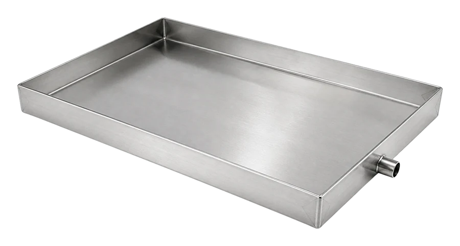
Specifications
The ranges below are what we have made and supplied for HVAC and data-centre projects. Anything outside them we make to drawing.
| Item | Pioneer drip trays |
|---|---|
| Materials |
|
| Sheet thickness | 0.8 mm (22 G), 1.0, 1.2, 1.5, 1.6 (16 SWG) and 2.0 mm |
| Edge (collar) height | 30, 50, 63 (2½ in), 75 and 100 mm |
| Pipe-run trays | 100, 150, 250, 300, 500, 600, 700 and 750 mm wide |
| Lengths | Up to 5000 mm per tray; joined with couplers into continuous runs |
| Equipment pans | Made to the unit size plus a margin, for example 750×750, 1200×750, 1400×750, 1460×1070, 970×550, 1460×820 and 2800×800 mm |
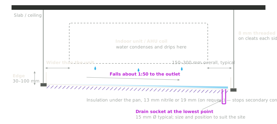
| Drain | 15 mm Ø drain socket typical; size, position and hose point to suit the site |
| Fall to drain | About 1:50 on approved shop drawings |
| Joints | Plate couplers 25 × 200 × 2 mm, 4 × M8 fasteners per coupler; SS 304 fasteners for stainless trays |
| Hanging | Cleats for 8 mm threaded rods, or L-clips and 30 × 30 × 5 mm angles |
| Insulation (on request) | 13 mm nitrile rubber or 19 mm insulation under the pan |
| Raw material | JSW / TATA sheet |
| Tolerances | Length ±10 mm, width ±3 mm, height ±2 mm |
| Documents | Datasheet and GA drawing for approval; test certificates with the supply |
Choosing the material
| Material | Choose it when |
|---|---|
| SS 304 | The tray must stay clean and rust-free for the life of the building — data halls, pharma, food, and anywhere a leak would be costly. |
| Hot-dip galvanised | The specification asks for a heavy zinc coat and rules out electroplated GI. Hot-dip galvanising lays down a much thicker zinc layer than electro-galvanising. |
| Pre-galvanised GI | HVAC units inside buildings. Specify the zinc: 120, 180 or 275 GSM. 275 GSM is the same coating US specifications call G90. |
| Powder-coated, epoxy-coated GI or PPGI | You want a painted barrier over the zinc, or a colour that matches the services. |
| Epoxy-coated aluminium | Large pans where weight on the slab or the hangers matters. |
Getting the size and slope right
A drain pan only works if water always has somewhere to go. ASHRAE Standard 62.1 asks that a drain pan:
- slopes at least 10 mm per metre (⅛ inch per foot) toward the outlet, or otherwise drains freely with the fan on or off;
- has its outlet at the lowest point, large enough not to overflow;
- has a P-trap or other seal where the pan sits under negative pressure;
- catches the full width of whatever drips, and stays reachable for cleaning.
The approved shop drawings our trays are made to use a fall of about 1 in 50 — 20 mm per metre, twice the ASHRAE minimum — and a tray roughly 150 to 300 mm larger than the unit overall. A 900 × 450 mm indoor unit, for example, gets a 1200 × 750 mm tray.
Under chilled-water units the pan itself gets cold and can sweat. That is why we offer trays with 13 mm nitrile or 19 mm insulation underneath.
Drip trays in data centres
Liquid cooling has brought water back into the white space. Data-centre specifications now call for drip trays under secondary-fluid and chilled-water pipework in the data hall, under pipe manifolds and flushing lines, and in both hot and cold aisles.
- Tray sections joined into one continuous tray, so water flows to the drains without being stopped at a joint.
- Hot-dip galvanised or SS 304 sheet, often with the edge turned up 63 mm (2½ in) or 100 mm (4 in).
- Room in the tray for the leak-detection probes or sensing cable your BMS contractor fits.
We make the trays to the pipe routes on your layout, and the wire mesh and ladder trays for the same hall. See cable trays for data centres.
Specification clauses for your BOQ
For consultants: copy a clause into your BOQ or technical specification, then adjust sizes and quantities to your schedule. Words in [brackets] are alternatives.
Data centre pipework — SS 304 / HDG
Chilled-water and liquid-cooling pipework in data halls
1. Drip trays shall be provided under chilled-water and secondary-fluid pipework where shown on the drawings, fabricated from SS 304 sheet [hot-dip galvanised steel] 1.2 mm [1.5 mm] thick.
2. Trays shall have a turned-up edge of 63 mm [100 mm] and shall be joined with plate couplers into one continuous tray that drains to the outlets.
3. Tray lengths shall be up to 5000 mm, width as per the pipe routes on the drawings.
4. Each tray run shall fall about 1 in 50 to drain sockets at its low points; drain size and position as per the drawings.
5. Space shall be left in the tray for leak-detection cable or probes where specified.
6. Make: Pioneer Cable Trays or approved equivalent.
HVAC units — GI / aluminium pans
AHUs, FCUs, VRF ductable and cassette units
1. Drip trays shall be provided under each indoor unit where shown, fabricated from pre-galvanised steel sheet 275 GSM [SS 304 / aluminium] 0.8 mm [1.0 mm] thick.
2. Each tray shall be larger than the unit footprint by 150–300 mm overall, with an edge of 50 mm [75 mm].
3. The base shall fall about 1 in 50 [not less than 10 mm per metre, as per ASHRAE 62.1] to a 15 mm drain socket at the lowest point.
4. Trays under chilled-water units shall have 13 mm nitrile rubber insulation underneath [where specified].
5. Trays shall be hung on 8 mm threaded rods from cleats on each side.
6. Make: Pioneer Cable Trays or approved equivalent.
What to send for a quotation
- The unit list with sizes, or the pipe routes with lengths and widths.
- Material and finish, and the zinc coating (GSM) if GI.
- Sheet thickness and edge height.
- Drain size and position, and whether you need a hose point.
- How the tray will be hung, and whether it needs insulation.
- Quantities, site location and the date you need it on site.
We reply with a quotation, our datasheet and a GA drawing for approval.